Hardware and software
SPI-Simulyzer
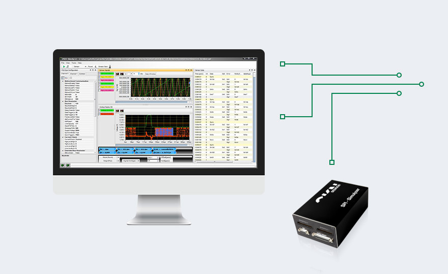
The SPI-Simulyzer is an interface box with which on the one hand data can be read out quickly and easily, and on the other hand simulation data can be used to actively intervene in the process.
Professional data simulation
Facts about the SPI-Simulyzer
In addition to the standard version, Seskion also offers modified versions as well as advanced hardware and software solutions for special measurement requirements.
- Standard Windows Gui application (optional): The protocol-specific Gui application offers a wide range of settings from the definition of signals, baud rates and error detection to trigger events. The visualization of the SPI bus communication facilitates troubleshooting and can also be easily saved. The SPI data is recorded with time stamps, whereby both import and export of data is possible.
- API-ANSI-C (included in the box)
- LabVIEW Lib (optional)
| Version | Date | Download |
| V1.21.4 | 16.07.2024 | SPI-SimulyzerSetup_V1_21_4.msi |
| V1.19.11 | 20.06.2021 | SPI-SimulyzerSetup_V1_19_11.msi |
| V1.19.8 | 01.12.2020 | SPI-SimulyzerSetup_V1_19_8.msi |
| V1.17.8 | 27.08.2018 | SPI-SimulyzerSetup_V1_17_8.msi |
| V1.17 | 10.11.2016 | SPI-SimulyzerSetup_V1_17.msi |
| Interfaces | USB 2.0 and connections for control unit and sensor |
| Power supply | via USB or external plug Power supply unit |
| Compatible systems | Windows-7 +10, Microsoft .NET Framework 2.0, Linux (only API, no GUI) |
| Recording options | Digital recording of the SPI, interfaces with 48 Mega-Samples per second |
| Data export | .csv-file (Excel) and .tdms-file (NI) |
| SPI Baud rates | as control device up to 16 MBit/s, as sensor up to 8 MBit/s |
| Modes | Out-Frame or In-Frame SPI |
Application Notes:
HiL-Setup with PSI5, SPI and SQUIB
Simulyzer-Software Operating Help
Optional 2nd-Channel or CAN-Interface
How to install Seskion License
Instructions Simulyzer LabView Library
Helpful Links:
Simulyzer-Box
2.1001 SPI-Simulyzer USB-Box V2.1, 1-channel, single-ended interfaces, 1.2V..5.5V, for analysis + simulation with DLL
2.1101 SPI-Simulyzer USB-Box V2.0, 1-channel, LVDS-Interfaces for analysis + simulation with DLL
Optional hardware additions
2.2001 Optional CAN Interface – SPI Simulyzer
2.2002 Optional 2nd SPI channel analysis + sensor simulation
Software licenses
2.3001 Windows Software Package SPI Simulyzer Analysis + Sensor Simulation (Simulyzer-Box or PC-ID bound license)
2.3002 Software license for SPI sensor model; per PC workstation and per sensor model. (Simulyzer-Box or PC-ID bound license)
Additional
2.4001 SPI-Simulyzer distribution board for controller and 3 interfaces with 3x ribbon cable
2.4002 SPI-Simulyzer distribution board -universal- for ECU and 1 interface
2.4003 SPI-Simulyzer distribution board for ECU and 1 interface with ribbon cable
2.4101 SPI-Simulyzer LVDS-single ended Pod with 2m cable
9.0001 Optional warranty extension of the Simulyzer box to 3 years
9.0011 LabView-2016 Library, 32- or 64-bit. PC-ID or Box-SN bound license
9.0012 LabView-2016 Library, 32- or 64-bit. Company license
Serial Peripheral Interface
The Serial Peripheral Interface (SPI) is a common bus system in automotive sensor technology. ECU and peripheral sensors are connected to each other according to the master-slave principle. Each station is connected to the Serial Clock (SCLK), MISO and MOSI lines. The master synchronizes the communication via the serial clock.
HiL-Simulation for Airbag ECU
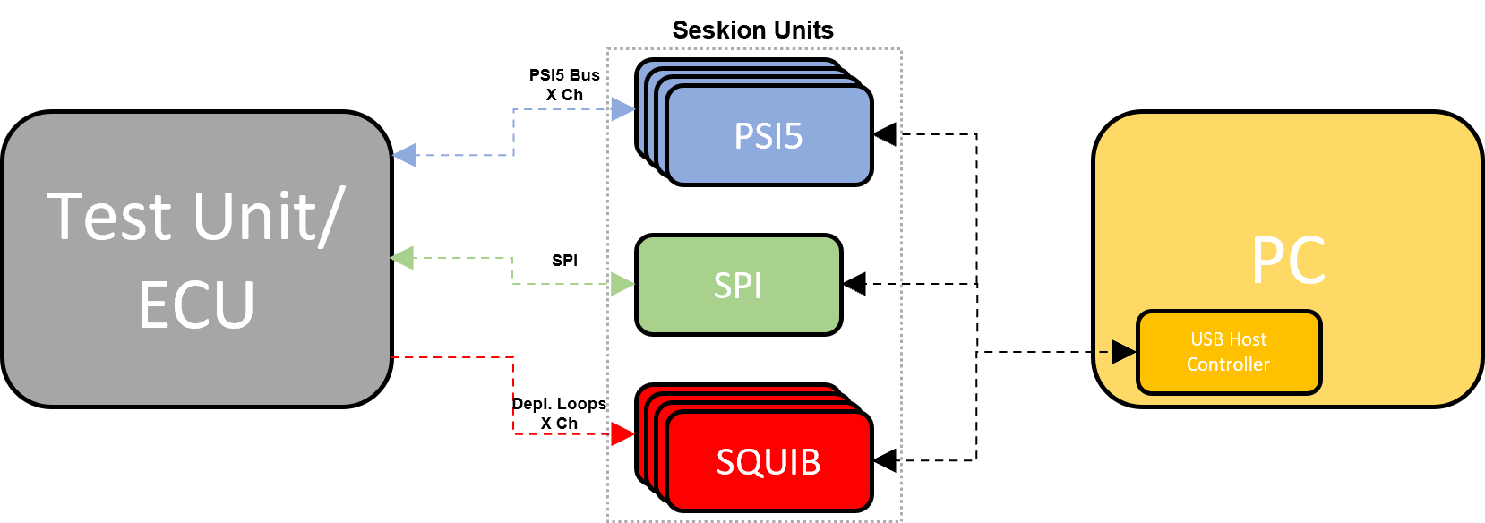
To generate a complete HIL simulation for an airbag control unit, the internal acceleration sensor signals of the control unit (SPI) and the peripheral acceleration and pressure sensor signals (PSI5) must be connected. Also the ignition timing can be measured and analyzed by using the SQUIB box. Furthermore, a PC system connected to the simulators via a USB port/network is used for data processing.
Often up to 6 or more PSI5-Simulyzer are operated together with several SPI-Simulyzer. For coordination there is a superordinate configuration, which determines which Simulyzer is used, which signal traces are used by which Simulyzer and which detailed configurations are to be used with the bus parameters. By using the superordinate configuration, the operation of the API is very simple. A continuous control of the sensor signals can also be made.


