After recording is started, the circular buffer is filled
(if required, the oldest data is overwritten in a constant loop).
During this period, the data can be seen as a constantly changing set
of numbers or curves in the display window.
Recording is stopped using one of the following trigger types:
Error
Combined error types can be selected.
Threshold
Exceeding or falling below a defined trigger threshold relating to the data value.
External triggering
The trigger input has TTL levels.
Manual triggering
Stop button is pressed .
A selectable number of data sets is recorded after triggering.
The time before and after the trigger can be entered in the subsequent display.
An impulse is created on the trigger output (TTL level) at the time of triggering.

Settings of the trigger data for the analog signals.
The following possibilities are available:
Mode: At mode Norm it will be triggered on the values
of the fields Edge and Signal.
At mode Auto the signal will be displayed continuously.
Edge: The trigger will be on the positive or negative or both slopes.
Signal: Following trigger signals are available:
voltage (trigger by cross line)
current (trigger by cross line)
external injected signal
The settings of the trigger is done in pin configuration
Data trigger (synchronous to the data trigger).
Offset [μsec]: Time spare after the trigger event when the recording is started.
Hold [μsec]: Time spare during the recording is done.
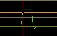
The trigger point is displayed as a cross line in the presentation window.
This enables a direct modification of the trigger point.
For a well arranged presentation the trigger data can be displayed or hidden.