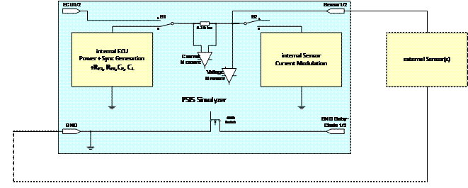
The general structure of the PSI5-Simulyzer box includes 5 basics:

PSI5 voltage and current are measured in all modes.
All GND potentials are the same except the GND Daisy-Chain 1 and 2.
In the single modes the electronic switch S1 and S2 are controlled as follows:
|
Working mode |
Position S1 |
Position S2 |
|
Passive mode |
1 |
1 |
|
ECU mode |
2 |
1 |
|
Sensor mode |
1 |
2 |
|
Simulation mode |
2 |
2 |
The PSI5-Simulyzer has four working modes:
Working mode - Sensor -
The Simulyzer acts as 1 or max. 6 sensors, meaning all sensor BUS parameters will be simulated.
Working mode - ECU -
The Simulyzer acts as control unit (ECU), meaning the ECU start conditions will be simulated and a synchonous impulse will be generated. Further more the sensors are provided with supply voltage.
Working mode - Passive -
The Simulyzer records the bus communication between a real ECU and connected sensors.
Working mode - Simulation -
The Simulyzer documents the bus communication at which point the ECU as well as the sensors will be simulated (intended only for training purposes).